
The designed amplifier can be used for the microwave applications which include weather radar, satellite communication, wireless networking, mobile, and TV.1498 1869 5 2 4 1 96/1 96/1 2 8 8 8 8 Paint.NET v3. Inter-modulation distortion is-56.919dBc which is less than-50dBc with 10dBm input power.

The designed amplifier is stable over the bandwidth (K>1). The simulation results showed an input return loss (S11) which less than-10dB, and gain (S21) is higher than 10 dB over the entire frequency band and considers as flat as well. Advanced Design System software used as a simulation tool to simulate the designed wide-band power amplifier. Class-A topology and ATF-511P8 transistor are used in this design. This paper presents the design of wide-band power amplifier which combined with parallel coupled line band pass filter at the input and output of power amplifier to allow the only required frequency band to pass through the power amplifier. RF power amplifiers are one of challenging blocks in designing radio frequency transceivers, this is due to non-linearity behavior of power amplifiers that leads to inter-modulation distortion. Therefore, the use of a modulated signal over a CW signal may have additional benefits.

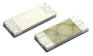
The results obtained demonstrate that energy recovery systems can use modulated signals. An efficiency of 72.325% and 45.935% is obtained with a 16 QAM modulated input signal for the operating frequencies, respectively, 69.979% and 54.579% for 8PSK. Conventional Wilkinson dividers are periodic at all odd harmonics as shown in Figure 5, but miniaturized circuits operate as a power divider only at f0. A peak of 67.041% and 49.089% was reached for 2.45 and 5.8 GHz, respectively, for CW as the input signal. Wilkinson dividers fabricated on HRS and However, the bandwidth of the power divider around the design frequency, fo, does not fully describe the circuit characteristics. According to the comparison with dual-band rectifiers presented in the literature, the designed rectifier is a high-efficiency rectifier for wide RF power input ranges. Second, operate with a wide input power range using the Wilkinson power divider (WPD) and two different rectifier diodes (HSMS2852 and SMS7630) instead of using active components. First, work with modulated input signal sources instead of only continuous waveform (CW) signals. This paper presents a new rectifier design for radio frequency (RF) energy harvesting by adopting a particular circuit topology to achieve two objectives at the same time.


 0 kommentar(er)
